


Why Does a Drone Battery Voltage Sag Under Payload? Causes, Risks and Battery Selection
October 15, 2026
Why does drone battery voltage drop under payload? This guide explains drone battery voltage sag causes, how to distinguish normal behavior from faults, how to check ESC and flight-controller readings, and how to choose a suitable UAV battery pack.
Table of Contents
If your drone shows a sharp battery voltage drop during loaded takeoff but the voltage recovers after reducing throttle, the cause may be increased current demand combined with battery internal resistance. However, wiring losses, battery condition and inaccurate flight-controller voltage readings should also be checked before assuming the battery itself is faulty.
This behavior is known as drone battery voltage sag. Some voltage drop under load is normal, but excessive sag can trigger low-voltage warnings, reduce available propulsion power and interrupt UAV operations.
For payload-carrying drones, the most useful approach is to examine current and voltage together. The goal is not to eliminate every voltage change, but to identify whether the battery, electrical connections and monitoring system can support the aircraft's actual operating requirements.
This guide explains why voltage sag occurs, how to distinguish normal battery behavior from potential faults, and when a different UAV battery pack configuration may be needed.
What Is Drone Battery Voltage Sag?
Drone battery voltage sag is the reduction in terminal voltage that occurs when a battery supplies electrical current.
When a lithium battery is disconnected from a load and allowed to rest, its open-circuit voltage reflects its electrochemical state. Once the aircraft's motors and onboard electronics draw current, terminal voltage normally decreases.
Part of this reduction results from internal resistance. Additional voltage changes are caused by electrochemical polarization, which depends on discharge duration, temperature and state of charge.
A simplified relationship is:
Voltage Drop (V) ≈ Current (A) × Effective Resistance (Ω)
For example, assume a battery system has an effective resistance of 20 milliohms (0.020Ω). At 40A, the approximate resistive voltage drop is 0.8V. When current rises to 100A, the calculated drop increases to 2.0V.
The additional 1.2V difference illustrates why higher electrical demand can produce a more noticeable voltage reduction without any immediate change in battery condition.
These are theoretical values, not measured specifications for a particular UAV battery. Actual voltage behavior includes time-dependent electrochemical effects and may vary as the battery discharges.
Why Does Drone Battery Voltage Drop When Payload Increases?
Adding payload increases the thrust required to keep a multirotor UAV airborne. To generate that additional thrust, the propulsion system generally draws more electrical power.
At a given voltage, increased power demand normally requires increased current. Higher current creates a larger voltage drop across the battery's internal resistance and other resistive parts of the electrical system.
This explains why a drone may show stable voltage during a light-load test but experience pronounced voltage sag when carrying a camera system, inspection equipment or agricultural payload.
The effect can be more noticeable during takeoff and climbing, when the propulsion system must produce enough thrust to support the aircraft and accelerate it vertically.
Importantly, payload mass does not directly reduce battery voltage. The change occurs because the aircraft requires additional electrical power to support and operate the payload.
Powered payloads may also draw current independently of the propulsion system. As a result, two payloads with similar mass can create different electrical demands.
How Current and Voltage Change During a UAV Mission
The relationship becomes easier to understand when voltage and current are viewed together across different operating phases.
Figure 1: Illustrative UAV Battery Current and Voltage Under Changing Load
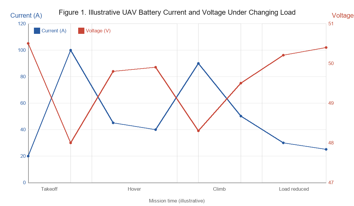
Figure 1. Illustrative UAV battery current (A) and voltage (V) under changing load. The example is conceptual, not measured flight data, and does not represent any YATTOX product.
In the conceptual example, current increases sharply during loaded takeoff, decreases during stable hover, rises again during rapid climbing and falls when the load demand is reduced. Battery voltage shows the opposite general response.
The example is illustrative rather than measured flight data. The values are not associated with any YATTOX product, and the operating stages do not represent equal time intervals.
Actual flight logs should include synchronized voltage, current and time measurements, allowing engineers to determine whether a voltage drop corresponds to a temporary current peak, a sustained operating load or another electrical condition.
Battery Internal Resistance
Every lithium battery cell has internal resistance, which contributes to voltage loss during discharge.
A complete pack's effective resistance depends on its cell characteristics, series and parallel arrangement, electrical connections, temperature and operating condition. Differences between cells may also affect pack behavior.
At high current, even relatively small resistance values can produce meaningful voltage drops.
This is why two batteries with identical nominal voltage and capacity may behave differently under the same load. Cell design, pack construction and internal resistance can influence the voltage actually available to the propulsion system.
As a battery ages, internal resistance may increase, making voltage sag more noticeable during demanding operations.
High Current During Takeoff and Climbing
Takeoff and climbing are often among the most demanding phases for a payload-carrying multirotor.
The motors must provide enough thrust to lift the full aircraft mass while maintaining attitude control and responding to changing flight conditions.
If current demand approaches or exceeds the practical operating capability of the battery, voltage sag may become significant.
The voltage may partially recover during lower-power flight because current demand decreases. This recovery does not prove the battery is healthy, but it does suggest that the voltage change is related to load.
Engineers should therefore compare takeoff current with the pack's verified continuous and peak discharge capabilities rather than judging the battery from a single voltage reading.
Battery State of Charge and Temperature
Voltage sag also depends on the battery's state of charge and temperature.
As a battery discharges, its operating voltage changes. Near the lower end of the usable state-of-charge range, additional voltage sag may bring terminal voltage closer to the aircraft's warning or protective thresholds.
Cold conditions can increase battery resistance and limit power delivery. Elevated temperatures can create other concerns, including accelerated aging and thermal stress.
Consequently, a pack that performs acceptably when warm and fully charged may behave differently during a cold-weather mission or near the end of discharge.
How Much Voltage Sag Is Normal for a Drone Battery?
There is no single voltage-drop value that is acceptable for every UAV battery.
A 1V decrease represents a different proportion of total voltage for a 4S battery than for a 12S pack. Current, temperature, battery condition, discharge duration and measurement location also influence the result.
The appropriate question is whether the loaded voltage remains within the operating requirements of the complete aircraft.
A temporary voltage drop should be distinguished from a potentially unsafe condition.
Voltage may recover after throttle reduction because resistive losses decrease and electrochemical polarization relaxes. However, the battery has not recovered the energy already consumed during flight.
Similarly, normal-looking voltage after landing does not establish that the pack maintained acceptable voltage or temperature throughout the mission.
What Risks Can Excessive Battery Voltage Sag Create?
Excessive voltage sag can reduce the electrical operating margin available to motors, ESCs and other aircraft systems.
If bus voltage becomes too low, the propulsion system may be unable to provide the requested power under demanding conditions. Depending on the aircraft's control architecture, this can affect thrust response and flight performance.
Low-voltage warnings or failsafe responses may also be triggered.
For example, ArduPilot's battery failsafe system can be configured to respond to sustained low voltage or low estimated remaining capacity. Its documented behavior depends on the configured thresholds, timing and selected failsafe actions.
These settings should be based on the particular aircraft and battery system rather than a universal voltage figure.
Excessive current can also produce substantial resistive heating.
The simplified relationship is:
Resistive Power Loss (W) = Current² (A²) × Resistance (Ω)
At an illustrative resistance of 20 milliohms, 50A produces approximately 50W of resistive loss, whereas 100A produces approximately 200W.
These calculated losses are not battery temperature measurements. Actual heating depends on where the resistance occurs, how long current flows and how effectively heat is dissipated.
Nevertheless, the relationship explains why voltage sag and temperature should be evaluated together during high-current UAV operation.
How Can You Diagnose Drone Battery Voltage Sag Under Load?
An effective diagnosis begins with measurements rather than immediately replacing the battery.
A voltage warning may result from a genuine decrease in battery terminal voltage, losses in the power distribution system or inaccurate voltage reporting.
These causes require different corrective actions.
A practical diagnostic process includes four steps:
- Record battery voltage and current together. Review synchronized measurements during low-load operation, loaded takeoff, hover and climbing. Look for voltage changes that correspond to increased current demand.
- Compare equivalent operating conditions. Where safe and permitted by the test procedure, compare results using similar states of charge, battery temperatures and aircraft configurations. This helps distinguish load-related changes from differences in battery condition.
- Inspect the electrical power path. Check connector condition, cable suitability, terminals, power distribution components and any abnormal heating. Suspected electrical faults should be inspected by qualified personnel with the system safely de-energized.
- Evaluate battery condition and specified limits. Compare actual current demand against the battery's documented discharge capabilities. Review age, temperature, available cell-level information and any known history of abnormal voltage behavior.
Measurements should be obtained through suitable, correctly rated instrumentation. High-current UAV power systems should not be probed or modified casually.
When an electrical fault is suspected, controlled ground diagnostics should take priority over repeated flight tests. A battery or connector with evidence of damage, overheating or intermittent power delivery should not be returned to service until the issue has been resolved.
| Observed Behavior | Possible Explanation | Recommended Check |
|---|---|---|
| Small drop when motors start | Normal load-dependent response | Compare with expected loaded voltage |
| Sharp drop during loaded takeoff | High current or excessive system resistance | Check current demand and electrical connections |
| Voltage recovers after reducing throttle | Load-related voltage sag | Review synchronized voltage and current |
| Sag becomes progressively worse | Aging, temperature or connection changes | Compare battery condition and operating history |
| One cell group drops more than others | Possible imbalance or cell degradation | Check available cell-level measurements |
| Sudden voltage loss or intermittent power | Possible electrical connection or component fault | Stop operation pending inspection |
| Telemetry voltage differs from independent measurement | Possible monitoring or calibration problem | Check power module and sensor configuration |
These observations indicate possible investigation paths, not definitive fault diagnoses. Several issues may occur simultaneously.
Could the ESC or Flight Controller Be Causing the Voltage Warning?
Not every low-voltage warning means that battery terminal voltage has fallen by the amount displayed in telemetry.
The battery terminals, ESC power input and flight-controller voltage display represent different measurement points or signal paths.
At the battery terminals, a calibrated measurement indicates the voltage delivered by the pack at that location. At the ESC input, the measurement can also reflect losses across cables, connectors and power distribution components.
Flight-controller telemetry may obtain battery voltage through a power module, voltage sensor, digital power monitor or supported ESC telemetry interface. Its accuracy depends on the installed hardware and correct configuration.
A useful diagnostic distinction is:
- Case 1: Measured battery terminal voltage falls substantially under load. The investigation should consider battery resistance, current demand, temperature and pack condition. Voltage losses in the wider electrical system may still contribute to downstream symptoms.
- Case 2: Battery terminal voltage remains relatively stable, but voltage at the ESC input falls. The power path between these points should be investigated for excessive resistance, inappropriate component ratings or connection faults.
- Case 3: Independent voltage measurements appear normal, but flight-controller telemetry reports a much lower value. The voltage monitor, calibration settings, supported measurement range, wiring and telemetry source should be checked before concluding that the battery is faulty.
Official ArduPilot power-module documentation describes battery voltage and current monitoring as functions that depend on correctly configured hardware and calibration. Its battery failsafe documentation also explains how voltage thresholds, timing and monitored voltage sources affect protective actions.
An ESC can contribute to genuine high current demand if its operating conditions or connected propulsion components are abnormal. However, the presence of a low-voltage warning does not independently establish an ESC fault.
Likewise, a flight controller may report a measurement or initiate a protective response without being the physical source of the battery's resistive voltage loss.
The engineering objective is to identify whether the issue involves actual power delivery, voltage sensing or both.
Is the Problem the Battery, Connector or Aircraft Load?
The electrical path from the battery to the propulsion system includes more than battery cells.
Connectors, cables, terminations, protection components where applicable and power distribution hardware can introduce additional resistance.
A battery with suitable internal resistance may still experience excessive downstream voltage loss if the connection path is unsuitable.
Conversely, a correctly installed electrical system cannot compensate for a battery that lacks the required current capability.
When available, comparisons between correctly measured battery terminal voltage and downstream voltage can help isolate the location of the loss.
These findings indicate possible investigation paths, not definitive fault diagnoses. Several issues may occur simultaneously.
For example, additional payload may increase current demand while an aging pack and resistive connector amplify the resulting voltage drop.
This is why replacing the battery without checking the complete electrical path may fail to resolve the original symptom.
| Diagnostic Finding | Primary Area to Investigate |
|---|---|
| Current rises sharply and battery terminal voltage falls | Battery response to load and propulsion demand |
| Large voltage drop at moderate current | Pack condition, resistance or electrical connections |
| Large difference between pack and ESC-input voltage | Cables, connectors or distribution components |
| Telemetry disagrees with calibrated measurements | Voltage sensing, configuration or monitoring hardware |
| Voltage sag worsens in cold conditions | Temperature-dependent battery performance |
| One monitored cell group behaves differently | Cell consistency or degradation |
| Sag increases as the battery ages | Capacity loss and increasing resistance |
Can a Higher C-Rating Reduce Drone Battery Voltage Sag?
A higher discharge rating may help when the existing battery cannot adequately support the required current. However, C-rating is not a direct measurement of internal resistance or voltage stability.
A common relationship is:
Rated Current (A) = Battery Capacity (Ah) × C-Rating
A 30Ah battery with a published 5C continuous discharge rating therefore corresponds to 150A of stated continuous current capability.
At 10C, the calculated current is 300A.
These figures describe current ratings under the manufacturer's specified conditions. They do not independently establish the internal resistance, loaded voltage, temperature rise or acceptable voltage sag of a particular UAV battery pack.
Peak-discharge ratings also require clarification of the permitted duration, temperature and other operating conditions. A 10C peak rating must not be treated as permission for continuous operation at 10C.
Two packs with the same capacity and C-rating may still show different voltage behavior because of differences in cell construction, resistance, operating temperature and pack integration.
What Do YATTOX 30Ah Semi-Solid-State Battery Specifications Show?
YATTOX publishes several voltage configurations within its 30,000mAh semi-solid-state battery series.
The listed products provide an example of how capacity, voltage, discharge ratings and connector options are presented for UAV battery selection.
Source: YATTOX 30,000mAh Semi-Solid-State Battery. Values represent published specifications, not measured voltage-sag performance.
| Specification | Published YATTOX 30Ah Data |
|---|---|
| Battery capacity | 30,000mAh / 30Ah |
| Configurations | 6S1P, 8S1P, 12S1P, 14S1P |
| Nominal voltage | 22.2V, 29.6V, 44.4V, 51.8V |
| Continuous discharge rating | 5C / 150A |
| Peak discharge rating | 10C / 300A |
| Connector options | XT90-S, QS8, AS150U |
Suppose an aircraft requires 100A during a particular operating phase. The published 150A continuous current rating may provide an initial reference for evaluating current capability.
However, this comparison does not prove that the battery will maintain a particular terminal voltage at 100A or that all available connector options are appropriate for that current in every installation.
Further evaluation should include the relevant discharge-test conditions, continuous-load duration, battery temperature, loaded voltage and electrical interface limits.
The same principle applies to peak current. A stated 300A peak capability must be checked against its permitted duration and operating conditions before it is considered suitable for the aircraft.
For industrial UAV procurement, published C-ratings should be treated as selection inputs rather than substitutes for complete-pack validation.
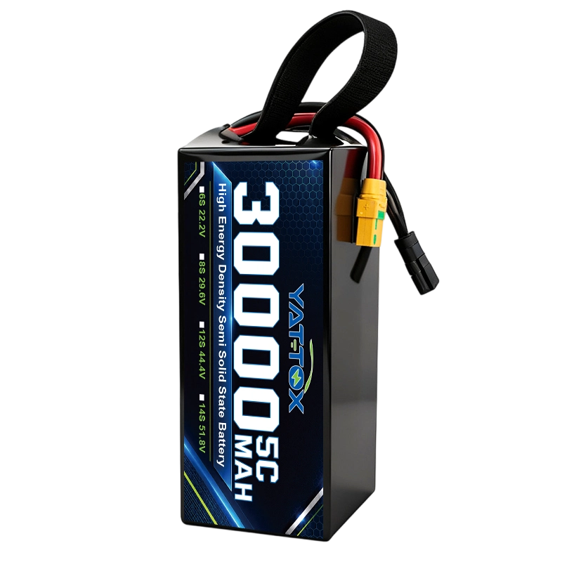
YATTOX 30,000mAh semi-solid-state UAV battery pack, published with 5C continuous and 10C peak discharge ratings across 6S1P to 14S1P configurations.
How to Choose a Replacement UAV Battery After Excessive Voltage Sag
When an existing drone experiences excessive voltage sag, the next step is not automatically to install a larger battery.
A replacement should be selected according to the cause identified during diagnosis.
If voltage falls mainly because current demand exceeds the pack's practical operating capability, the replacement may need stronger discharge performance, lower effective resistance or a different cell and pack design.
If current demand remains within suitable limits but voltage loss occurs primarily in the cable or connector path, correcting the electrical integration may be more appropriate than replacing the cells.
If the flight-controller reading is inaccurate, sensor calibration or monitoring-system repair may resolve the reported problem without changing battery capacity.
For a confirmed battery limitation, the most useful selection data are the observed continuous and peak current, loaded voltage, temperature, original battery configuration and the duration of high-power events.
A replacement pack should be evaluated against the existing voltage platform, physical installation limits, electrical connections and required mission duration.
Battery mass remains important. Increasing capacity may improve available energy or power capability, depending on the design, but the additional weight can increase the power needed to support the aircraft.
Changing voltage platforms also requires system-level compatibility. A higher-voltage configuration can reduce current for the same electrical power under certain conditions, but it cannot be substituted into an existing UAV unless the propulsion system, ESCs, power distribution, electronics and charging equipment support it.
For projects that need a complete energy and payload calculation, heavy-lift drone battery sizing should account for total aircraft weight, power demand and usable mission energy.
For an aircraft already experiencing voltage sag, however, replacement selection should begin with the recorded fault conditions and the specific limitation established by testing.
How YATTOX Supports UAV Battery Power and Pack Integration
Battery voltage behavior depends on the combination of cell characteristics, pack architecture and electrical integration.
For UAV manufacturers and system developers, selecting a battery therefore involves matching the power source to the aircraft's actual operating conditions.
YATTOX provides UAV battery solutions with configurable voltage, capacity, discharge characteristics and installation requirements. Its product range includes LiPo, lithium-ion and semi-solid-state battery options for different UAV operating profiles.
When evaluating a project affected by excessive voltage sag, the engineering discussion can focus on three areas:
- Discharge-performance matching: Compare measured continuous and peak current demand with suitable cell and pack characteristics, including voltage behavior under representative loads.
- Electrical and structural integration: Review voltage configuration, installed weight, pack dimensions, cable requirements and connector compatibility with the aircraft's existing power system.
- Cell and pack quality control: Consider cell consistency, voltage inspection, internal-resistance testing and production traceability as part of battery manufacturing and evaluation.
YATTOX's semi-solid-state battery solutions include in-house cell manufacturing capabilities, integrated cell-to-PACK development, open-circuit voltage inspection, internal-resistance testing and MES traceability.
These capabilities support manufacturing control and battery consistency evaluation. They do not independently establish a guaranteed voltage-sag value for every UAV configuration.
For a technical review, useful information includes the aircraft's existing battery voltage and capacity, payload weight, measured current demand, voltage behavior during takeoff and climbing, battery dimensions, connector requirements and operating temperature.
Where available, synchronized flight logs and independent voltage measurements provide a more reliable basis for identifying whether the project requires a different battery discharge profile, modified pack integration or further electrical-system troubleshooting.
How Can Excessive Drone Battery Voltage Sag Be Reduced?
The appropriate corrective action depends on the diagnosed cause.
When a battery lacks adequate power capability, engineers may need a different cell design or pack configuration that better supports the required current.
When excessive voltage loss occurs in connectors, cables or power distribution components, the electrical path should be inspected and corrected according to the equipment's design requirements.
If flight-controller voltage readings are inaccurate, the monitoring system should be verified and calibrated before battery performance is judged from telemetry alone.
Battery aging, cell imbalance and abnormal heating require a different response. Suspect packs should be assessed using the manufacturer's inspection and retirement criteria rather than repeatedly operated under high load.
For new UAV platforms, battery selection should be integrated with propulsion-system design and payload requirements early in development.
For existing aircraft, recorded current, voltage and temperature data should guide the corrective decision.
The objective is not zero voltage sag. It is reliable power delivery with loaded voltage, current and temperature remaining within the verified limits of the UAV and battery system.
Frequently Asked Questions About Drone Battery Voltage Sag
Why does my drone battery voltage drop when I increase the throttle?
Increasing throttle generally raises propulsion power demand and battery current. Higher current produces greater voltage loss across the battery's effective resistance and electrical connections. The resulting sag depends on battery condition, state of charge, temperature and operating load.
Is battery voltage sag normal in LiPo drones?
Yes. Some voltage sag is expected when a LiPo battery supplies current. However, a sharp or worsening voltage drop may indicate excessive electrical demand, increased internal resistance, poor connections or a battery that is unsuitable for the application.
Why does drone battery voltage recover after landing?
When current decreases, the resistive voltage drop becomes smaller and electrochemical polarization relaxes. Terminal voltage may therefore recover after landing. This does not restore energy already consumed during flight.
Can an ESC cause drone battery voltage sag?
An ESC or propulsion-system problem may contribute to abnormal current demand, which can increase genuine battery voltage sag. However, an ESC should not be identified as the cause from a voltage warning alone. Battery-terminal measurements, downstream voltage and relevant ESC data should be evaluated together.
Can a flight controller show incorrect battery voltage?
Yes. Incorrect voltage-monitor configuration, sensor calibration, incompatible monitoring hardware or measurement faults may produce inaccurate telemetry readings. The displayed value should be checked against appropriately obtained independent measurements.
Will a higher C-rating battery prevent voltage sag?
No. A higher C-rating may provide additional current capability, but voltage sag also depends on internal resistance, temperature, cell condition and electrical integration. C-rating alone does not guarantee a particular voltage under load.
Should I replace my battery if voltage drops during loaded takeoff?
Not automatically. First determine whether the voltage drop is real, whether current demand is excessive, and whether wiring or voltage monitoring contributes to the symptom. Battery replacement is appropriate when testing identifies a battery limitation that cannot be addressed through other system corrections.
Need a UAV Battery That Matches Your Payload and Power Requirements?
Excessive voltage sag may indicate a mismatch between battery discharge performance, aircraft power demand or electrical integration.
YATTOX supports customized UAV battery configuration and PACK integration for projects with defined voltage, capacity, current, weight and installation requirements.
Share your existing battery specifications, payload, measured current demand, voltage behavior under load and available installation space to discuss a suitable battery configuration.
Discuss Your UAV Battery Requirements
Explore YATTOX UAV Battery Solutions and semi-solid-state UAV batteries to compare published discharge, voltage and integration specifications for your platform.